Maybe you can search for


Company Overview
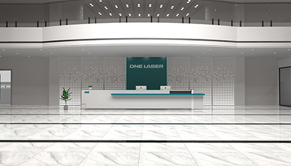
DNE LASER (Guangdong) Co., Ltd. (Brand name: DNE LASER), a
wholly owned subsidiary of Swiss Bystronic Group, is headquartered in Shenzhen with its production base located in Nanhai, Foshan.
wholly owned subsidiary of Swiss Bystronic Group, is headquartered in Shenzhen with its production base located in Nanhai, Foshan.
View more
Contact Us
For all business inquiries, partnership discussions and feedback,
please contact us via website form, 24-hour service hotline or email. Our team guarantees a prompt response within one business day.
please contact us via website form, 24-hour service hotline or email. Our team guarantees a prompt response within one business day.
View more
Join Us
We welcome talented professionals worldwide, offering attractive
pay, benefits, and clear career paths. Our collaborative culture drives innovation. Whether an expert or rising star, you'll thrive with us.
pay, benefits, and clear career paths. Our collaborative culture drives innovation. Whether an expert or rising star, you'll thrive with us.
View more

















Search
Close